
Projects Section
Aerial Triangulation
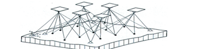
Project Inputs: 337 UltracamVexcelD photos with a GSD of 20cm, covering an area of 214 Km², Camera calibration report, Control Points, GPS / IMU data, Flight plan Index diagram
Project Scope:
The project required to Aero Triangulate the given project area with the help of GPS / IMU & Ground Control Points provided, within specified accuracy parameters. The AT deliverables were as following:
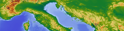
Digital Terrain Model (DTM)
Aerial Images, External Orientation Parameters (EO File), Camera Calibration Report, Tile Index with Area of Interest, Technical Specification Document, Tile naming scheme.
Total Area: 62 Km²
Total Area: 62 Km²
Orthophoto
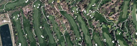
# of Photos with 10cm GSD: 259
# of photos with 40cm GSD: 4184
External Orientation Parameters (EO File), Camera Calibration Report, Tile Index with Area of Interest, Technical Specification Document, tile naming scheme, Project Shape files & client provided DTM
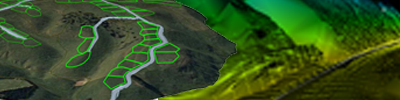
3D City Modelling
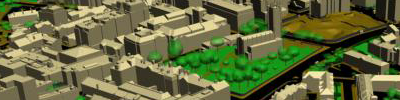
Input : Raw aerial images, camera report, ground control points & flight data.
Deliverable : 3D City Model
2D & 3D Topographical mapping
Project Inputs Raw aerial images, camera report, ground control points & flight data.
Project Scope:
HORIZONTAL ACCURACY:
95% of all well-defined features, as viewed in the stereo model, must be recorded in the digital data set within 30cm of the same position read on the best stereo model.
VERTICAL ACCURACY:
95% of all spot heights shall be accurate to 50 cm of the same position read on the best stereo model.
95% of all contours shall be accurate to one metre in height of their true elevation.
The accuracies specified above pertained to the ground not sufficiently obscured by vegetation cover.
LiDAR
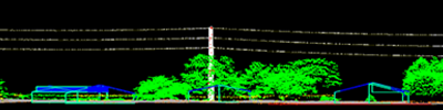
Project Inputs: LiDAR .LAS Tiles & .PTC file, Trajectory & Shape files, Tile Index with Area of Interest, Tile naming scheme & Technical Specification Document.
Project Duration: 12 weeks.
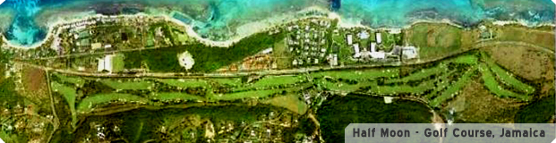
Golf Course Mapping